Kamagra gibt es auch als Kautabletten, die sich schneller auflösen als normale Pillen. Manche Patienten empfinden das als angenehmer. Wer sich informieren will, findet Hinweise unter kamagra kautabletten.
Imaging an adapted dento-alveolar complex
Imaging an adapted dento-alveolar complex
Ralf-Peter Herber1 , Justine Fong2, Seth A. Lucas1, Sunita P. Ho2*
1 Division of Orthodontics, Department of Orofacial Sciences, University of California, San Francisco, CA 94143, USA
2 Division of Biomaterials and Bioengineering, Department of Preventive and Restorative Dental Sciences, University of California San Francisco, San Francisco, CA 94143, USA
* Corresponding author; email address:
[email protected]
email:
[email protected],
[email protected],
[email protected],
[email protected]
Adaptation and resulting morphology of a rat dento-alveolar complex was imaged using various
imaging modalities. Complementary techniques including micro X-ray computed tomography combined
with 3D modeling using image processing, scanning electron microscopy, fluorochrome labeling,
conventional histology (H&E, TRAP), and immunohistochemistry (RANKL, OPN) elucidated the dynamic
nature of bone, the periodontal ligament-space and cementum in the rat periodontium. Tomography
illustrated structural adaptation in the calcified tissue and, electron microscopy allowed to study it at a
higher resolution. Ongoing biomineralization could be analyzed using fluorochrome labeling on tissue
sections from block specimens and attenuation profiles on virtual sections from tomography images.
Osteoclastic distribution as a function of anatomical location was illustrated by combining histology and
immunohistochemistry and tomography. While tomography and SEM provided past resorption related
events, future adaptive changes were deduced by identifying matrix biomolecules using
immunochemistry. Thus a dynamic picture of the dento-alveolar complex in rats was illustrated.
1. Introduction
The load bearing bone is a dynamic tissue and continuously adapts to changes in loads [1]. In the
periodontium, the cementum of a tooth is attached to the alveolar bone by the periodontal ligament
(PDL) and the root is contained within the alveolar bone socket. Cementum and bone are calcified
tissues of similar chemical composition, but cementum is far less dynamic [2]. The vascularized and
innervated PDL consists of basic constituents that resist and dampen mechanical loads. Different types
of collagen and non-collagenous proteins including polyanionic water attracting molecules, the
proteoglycans (PGs), all of which accommodate cyclic occlusal loads of varying magnitudes and
directions. Unlike other ligaments within the musculoskeletal system, the blood vessels in the PDL are
continuous with blood vessels in the endosteal spaces of bone [3]. Although PDL and bone are two
dissimilar tissues in physical and chemical properties, the continuity formed by blood vessels enables a
flow of nutrients and maintains cellular activity responsible for PDL turnover and bone remodeling.
Development and growth superimposed with functional loads [4] causing posterior lengthening of the
rat jaw [5] can contribute to PDL turnover, bone remodeling and load related modeling during the
lifespan of a rat. As a result it is thought that rat molars exhibit an inherent distal drift [6], but it
continues to be controversial [7, 8]. Regardless of the cause, the drift of the molars causes resorption of
bone located on the distal side of the root and bone formation located on the mesial side. To avoid
confusion, the distal side of the root and the adjacent alveolar bone are referred to as the distal root-
bone complex (bone resorption side) in this work and the mesial side of the root and adjacent bone as
the mesial root-bone complex (bone apposition side). Specific to this study are the various imaging
modalities implemented to investigate the physical, chemical and biochemical manifestation of distal
drift in the rat bone-PDL-cementum complex.
Numerous studies in the field of mineralized tissues related to dental research have used the rat
periodontium as a model to investigate adaptation of bone, PDL and root by applying many
perturbations, predominantly disease [9] and extraneous loads [10]. The perturbations especially affect
the bone-PDL and cementum-PDL attachment sites. Hence, it is important to know the baseline
parameters in the rat model before additional variables are imposed.
A great variety of imaging modalities have been used to study the dento-alveolar complex. In this
study we present an overview of commonly used imaging methods to investigate calcified tissues and
the PDL while addressing the plausible artifacts during specimen preparation, imaging and post
processing of experimental data. Micro X-ray imaging is one such popular method as it provides a three-
dimensional (3D) representation of organs and tissues. Micro X-ray imaging was used to study the
internal architecture of bone [11], tooth [12] and the bone-PDL-cementum complex [3] along with
resorption related changes of the root [13]. Additionally, it provides attenuation maps which can be
related to mineral density variations within calcified tissues [11]. Scanning electron microscopy (SEM) is
used to study tissue architecture at a relatively higher resolution, and in this study resorption related
bone [14] and root [15] morphology. Although not used in this study, the higher resolving power of a
transmission electron microscope (TEM) provides information about the inorganic crystal type and
morphology within a tissue matrix [16]. While most conventional SEM and TEM operate under high
vacuum mode, an atomic force microscope (AFM) can image site-specific regions within tissues at
ambient conditions facilitating nanoscale and microscale observations of tissue architecture under
hydrated conditions [17] with minimum specimen preparation [18]. AFM coupled with a
nanoindentation transducer can be used for mapping site-specific mechanical properties of tissues and
their graded interfaces [3]. Various spectroscopy techniques provide chemical composition of calcified
tissues exemplary Fourier transform infrared spectroscopy (FTIR) [19] and Raman micro spectroscopy
[20]. Complementing analytical techniques in the study of tissue architecture are numerous
conventional histological and immunohistochemical stains to identify cells relative to the spatial location
of biomolecules of interest. More specific to this study, this includes hematoxylin and eosin (H&E) [21,
22], tartrate-resistant acid phosphatase (TRAP) [23, 24] and immunohistochemistry antibodies for
receptor activator of nuclear factor κB ligand (RANKL) [25, 26] and osteopontin (OPN) [27, 28].
Fluorochrome labeling is another widely used technique to study the temporal growth of bone and
cementum [29, 30].
In this study micro X-ray tomography (Micro XCT™) was used to image and measure the anatomy,
physical and chemical properties of calcified tissues in 3D and locate resorption and remodeling related
events. Micro XCT™ data was complemented with (immuno-)histochemical studies to investigate
biomolecular events within the bone-PDL-cementum complex. Furthermore, combination of these
techniques performed consecutively on the same specimen allowed correlating the 2D histological
block sections within their original 3D structure, which had been virtually conserved as tomography
data, with the scans performed before specimen preparation necessary for histology, i.e. decalcification
and sectioning. Thus synergetic effects between imaging modalities were exploited to develop a
dynamic picture of the resorption and remodeling related events in the load bearing bone-PDL-
cementum complex. The combination of techniques presented herewith describes complex events in
the periodontium and illustrates potential mechanisms elucidating cause and effect relationships.
2. Materials & Methods
Maxillae from 7 weeks to 4 month old male Sprague Dawley rats were used. Rats were obtained
using animal tissue transfer according to guidelines of Institutional Animal Care and Use Committee
(IACUC), University of California San Francisco (UCSF).
2.1 Micro X-ray Computed Tomography
Entire heads or hemimaxillae were imaged using Micro XCT™. The occlusion was imaged using
whole heads, while the tooth-bone complex was imaged using hemimaxillae. After harvesting, all
specimens (N = 8) were placed in polymeric containers with 70% ethanol based phosphate buffer
solution, mounted on a specimen stage, and imaged at different magnifications and power as needed
using a Micro XCT-200 (Xradia Inc., Pleasanton, CA, USA). The fur from whole heads was removed, and
imaged under no load and loaded conditions. Static load applied with a polymeric wire was used to bring
the upper and lower jaws together in order to image rat occlusion using a 2x objective, at 90 kVp and a
power of 6 W. The maxillae were imaged at 2x and 4x and 75 kVp and a power of 6 W. Each tomography
was reconstructed from 3500 radiographic projections obtained from a full circle of 360° and exposure
times were adjusted to yield 6000 to 8000 counts per pixel of each recorded radiograph approximating
25% of the original X-ray intensity passing through the specimen and arriving at the detector. Associated
tomographies were reconstructed using reconstruction software (XMReconstructor, Version 7.0.2817,
Xradia Inc., Pleasanton, CA, USA). 3D images were post processed using the Xradia 3D viewer and
Amira® software (Visage Imaging Inc., Version 5.2.2, San Diego, CA, USA).
2.2 Scanning Electron Microscopy
Using thoroughly dried maxillae (N = 3), molars were isolated using forceps and the remaining bony
sockets were cut to separate bone from the mesial and distal complex. Bone and teeth were mounted
on SEM stubs and sputtered with gold. The specimens were examined using a SEM (S4300, Hitachi,
Tokyo, Japan) with an electron energy of 5 keV.
2.3 Histology
Intact hemimaxillae (N=5) were decalcified in 0.5 M EDTA solution for 3 weeks. The specimens were
dehydrated with 80%, 95% and 100% Flex alcohol (Richard- Allan Scientific, Kalamazoo, MI) before
embedding in paraffin (Tissue Prep-II, Fisher Scientific, Fair Lawn, NJ). They were sagittally sectioned on
a rotary microtome (Reichert- Jung Biocut, Vienna, Austria) using a disposable steel blade (TBF Inc.,
Shur/Sharp, Fisher Scientific, Fair Lawn, NJ). The paraffin serial sections were mounted on Superfrost
Plus microscope slides (Fisher Scientific, Fair Lawn, NJ) and deparaffinized with xylene.
2.3.1 Hematoxylin & Eosin Stain
The sections were stained with hematoxylin (Fisher Scientific, Kalamazoo, MI) and eosin (Fisher
Scientific, Kalamazoo, MI) [31]. The stained tissues were characterized using a light microscope (BX 51,
Olympus America Inc., San Diego, CA) and analyzed using Image Pro Plus v6.0 software (Media
Cybernetics Inc., Silver Spring, MD).
2.3.2 Tartrate-resistant Acid Phosphatase Histochemistry
Deparaffinized serial sections were used for TRAP staining. In brief, the method [32] included
treating the rehydrated specimens with 0.2 M acetate buffer, a solution of 0.2 M sodium acetate and 50
mM L(+) tartaric acid (Sigma-Aldrich, St. Louis, MO). After 20 minute incubation at room temperature,
napthol AS-MX phosphate and fast red TR salt were added followed by incubation at 37° C for 1 hour
with close monitoring under the microscope after the first half hour for bright red staining of
osteoclastic activity. The stained sections were washed in deionized water, counterstained with
hematoxylin and mounted with Immu-mount (ThermoScientific, Fremont, CA) for subsequent
examination under a light microscope as stated above. Multiple images were stitched together to
produce the resulting figure using Microsoft Research Image Composite Editor (Microsoft Corporation,
2.3.3 Immunostaining
In the method used [26], deparaffinized sections were rehydrated, digested with trypsin (Sigma-
Aldrich, St. Louis, MO) for ten minutes at 37° C and subsequently rinsed and washed in deionized water.
Specimens were incubated in blocking buffer (3% goat serum, 0.1% BSA in 1x PBS) and then in primary
antibodies polyclonal rabbit anti-RANKL (Santa Cruz Biotechnology Inc., sc-9073, Santa Cruz, CA) or
monoclonal mouse anti-OPN (Santa Cruz Biotechnology, Inc. Akm2A1, Santa Cruz, CA). Primary
antibodies were diluted to 1:50 in blocking buffer. Slides were stored at 4°C in a humidity case
overnight followed by washing three times for five minutes with 0.1% Tween-20 in PBS (PBST) and then
incubated with secondary antibodies. AlexaFluor 594 goat anti-rabbit (Invitrogen, A-11029, Carlsbad,
CA) was used to label polyclonal rabbit anti-RANKL and AlexaFluor 488 goat anti-mouse (Invitrogen, A-
11037, Carlsbad, CA) to label monoclonal mouse anti-OPN, at 1:300 (diluted in blocking buffer). Slides
were incubated in a dark humidity case for one hour at room temperature. Sections were washed three
times for five minutes with PBST and then stained with 1:10 000 trihydrochloride trihydrate (Invitrogen,
Carlsbad, CA) for ten minutes in the absence of light. Slides were rinsed twice with PBS and mounted
using Fluorogel (Electron Microscopy Sciences, Hartfield, PA). Stained tissues were visualized using
Eclipse E800 fluorescent microscope (Nikon Inc., Melville, NY). TRITC filter (540-565 nm) was used to
excite AlexaFluor 594 (abs. 590 nm, emit. 617 nm), FITC filter (465-495 nm) to excite AlexaFluor488 (abs.
495nm, emit. 519 nm), and DAPI filter (340-380 nm) to excite trihydrochloride trihydrate (abs. 358nm,
emit. 461 nm). Multiple images were stitched together as described above.
2.4 Fluorochrome study
Under regulation of the animal protocol No. AN083692 and AN080608-02 approved by the IACUC,
UCSF, 6 week (N = 3) and 4 month (N = 3) old male Sprague-Dawley rats were given intraperitoneal
injections with alternating tetracycline hydrochloride and alizarin red (both Sigma-Aldrich, St. Louis, MO)
on day 0, 3 and 7. According to the method used [29], 25 mg fluorochrome per 1 kg rat body mass was
diluted in 2% NaHCO3 to a concentration of 0.01 mg/µL before intraperitoneal injection. On day 8, rats
were sacrificed using CO2 gas and bilateral thoracotomy. Maxillae were dissected, fixed in 4%
paraformaldehyde overnight, sectioned sagittally using a low-speed diamond saw (Isomet, Buehler, Lake
Bluff, IL), and ground into 50 µm-thick specimens for viewing under the fluorescent microscope (Eclipse
E800, Nikon Inc., Melville, NY). FITC filter (465-495 nm) was used to excite Tetracycline HCl (abs. 390-
425 nm, emit. 525-560 nm) and TRITC filter (540-565nm) to excite Alizarin Red (abs. 530-560 nm, emit.
580 nm). Multiple images were stitched together as described above.
3. Results & Discussion
In 1870 Julius Wolff discussed the adaptation of bone due to mechanical forces [1]. The most
prominent force in the periodontium is the occlusal force that is applied primarily to grind the hard diet
that is fed to lab rats [33]. Within this adaption lies growth and function related changes in bone and
cementum, which will be illustrated through various imaging modalities.
Micro XCT™ allows 3D imaging of macroscopic objects with a microscopic resolution below 5 µm in
our setup. It is a noninvasive technique that requires minimum specimen preparation. Specimens can
be imaged under wet conditions preserving tissue structure. Data collected is suitable for post
processing to evaluate mineral density, resorption volumes, displacement fields using virtual sections at
no load and comparing them to the same sections under load, 3D spatial association of the root with the
bony socket at no load and under load are some of the results that can be extracted from the
tomographic data. Additionally, 2D images recorded with other techniques such as light microscopy can
be related to the 3D tomography image and 2D virtual sections and potential artifacts due to specimen
preparation can be identified. In this study we utilized, in particular, the ability of Micro XCT™ for
in situ
imaging i.e. under a static load, providing a 3D evaluation of the root association with bone. Morphology
and resorbed volumes of bone and roots, and resulting morphology were measured. Structural analysis
through the volume of a specimen can be performed using virtual serial section with no loss of
information and correlated with least interpolation. Additionally, X-ray attenuation with regards to
mineral density variations especially at the bone-PDL interface was investigated.
An approximate occlusal plane by bringing the jaws together is shown in Fig. 1 left. Furthermore, the
figure provides an approximation of various directions of functional loads exerted on the tooth relative
to the occlusal plane.
The micro-XCT images presented in Fig. 1-3 allow studying and describing the accurate anatomy of
the dento-alveolar complex. Accurate knowledge of the anatomy is necessary to spatially correlate 2D
measurements from other complementary studies by identifying landmarks and anatomical directions
within the dento-alveolar complex. Furthermore, comparative studies will help identify deviations from
baseline measurements due to external perturbations such as disease or load-mediate influences.
Finally, the 3D tooth-bone association will provide insights to form-function relationships and lead to the
design of future studies.
In general, a hemimaxilla contains one incisor and three molars. We focused our investigation on
the molars responsible for masticatory function. The crown of the 1st molar is the biggest with the
largest occlusal surface with the 2nd molar measuring approximately 2/3 and the 3rd molar 3/5 of the
length of the 1st molar. In all specimens a significant amount of occlusal wear commonly observed in rats
was noted. Fig.1 demonstrates enamel wear and exposed dentin on the occlusal surface. This could lead
to varying contact between opposing teeth and is a potential cause for altered biomechanics and
modeling related adaptation in the bone-PDL-cementum complex throughout the life-span of an
The 1st molar is located mesially and the 3rd molar distally. Often times the challenge lies in
identifying the anatomical directions of the specimen when only a part of it is imaged. Hence, certain
predefined anatomical features are used to assign directions. Lingual and buccal sides denote the
tongue and cheek-sides of the rat specimen, respectively. The bone around the molars is slightly curved
with the center of the curve toward the lingual side. The occlusal surface of all molars contains 2 or 3
enclosed depressions with the most mesial located predominantly in the lingual half. Additionally, the
roots on the lingual side are more uniform in appearance and more closely aligned. The 1st, 2nd and 3rd
molar have 5, 4 and 3 roots, respectively. Quite regularly the 3rd molar exhibits an additional but very
small 4th root. The majority of the roots are aligned in 2 parallel lines lingual and buccal from the mid-
sagittal section. The roots are not perpendicular to the occlusal plane, but exhibit a slight distal
inclination α of 10°-15°. The angle of inclination is measured at the root apex between the normal to the
occlusal surface and the root surface, as sketched in the most mesial root in Fig.1 bottom right.
According to the theory of Wolpoff [34], inclinations promote distal drift of the molars. At the age of 4
month, the roots are commonly not straight but exhibit mesial curvature along with increasing distal
inclination towards the root apex (Figs. 1-3). The mesial root of the 1st and the distal root of the 3rd
molar are exceptional cases as they are centrally located and strongly inclined mesially and distally,
respectively. Given such an anatomy, when in function, natural distal drift can also originate from
occlusal forces that create a distal force vector due to the distal inclination of the roots [34].
Interestingly, root inclination in humans and primates is mesial [8, 35] and a physiological mesial drift is
reported that enables closing of gaps due to development and function [36]. Based on the morphology
of the tooth-bone complex in rats, it is conceivable that occlusal loads will compress the PDL in the distal
root-tooth complex and simultaneously will result in PDL-tension in the mesial complex. This effect is
most dominant in orthodontics where compression sites in the PDL promote resorption and, tension
sites promote formation resulting in tooth migration in direction of the applied continuous force vector
[37]. Cyclic compression and tension of the PDL during mastication could promote bone resorption and
formation, respectively. Furthermore, it has been shown that different mechanical demands on the
tooth-bone complex either comparing experimental rat groups fed hard or soft diet [4], or within the
same rat, comparing compression and tension sites related to distal inclination of the roots (Fig. 2) do
affect the micro-scale structure of alveolar bone and macro-scale form of the bony socket.
Consequently, bone morphologies in the distal and mesial root-tooth complex of the same root are
inherently different as demonstrated in Fig. 2.
Bone of the distal complex contains concave-rounded pits separated by narrow sharp ridges,
resulting in a rough and pitted surface. This appearance is characteristic for distal bone and originates
from the osteoclastic resorption activity as was also demonstrated in SEM micrographs (Fig. 5) and
histological images (i.e. Fig. 6 and Fig. 7). The sizes of individual pits of approximately 50 to 100 µm in
diameter correspond well with the 35 to 100 µm sized rat osteoclasts [38]. A reconstruction of the bony
socket from the same Micro XCT™ scan is illustrated in Fig. 2c. The extent of the osteoclastic activity can
be observed as several resorption channels cut through the volume of the bone (Fig. 2c left).
Contrastingly, the bone from the mesial root-bone complex exhibits a smooth surface with convex-
rounded bony protrusions into the PDL-space. The bony protrusions are separated by recesses or
channels (Fig. 2). The channels can be related to blood vessel spaces which is indicated by their close
relation to red blood cells as shown in the H&E stained sections (Fig. 6). The convex protrusions can be
attributed to bone formation as demonstrated in the fluorochrome study (Fig. 4 right). Regardless, the
3D images of bone of both sides demonstrate continuity of the blood vessels between PDL-space and
bone via the described channels (Fig. 2c). Several histology sections in this study also support this
observation in particular Fig. 6c top right.
The roots also exhibit a significant structural anisotropy. The root surface separated by a 100 µm
thick PDL from the resorbed bone in the distal root-bone complex also exhibits resorption pits (Fig. 2).
The 3D images of the distal roots of a second molar in Fig. 3 viewed from different angles illustrates the
distribution of resorption pits on the root. Resorption pits are less frequent than on bone, small and can
be identified predominantly in the coronal region of the root in primary cementum. While the mesial
surfaces of the coronal thirds/halves of the roots typically show a regular morphology, on the coronal-
distal portion of the roots several pits can be identified. The apically located secondary cementum
shows an overall high roughness obscuring minor pits on all sides. The rather rough appearance of the
secondary cementum in the apical part of the root has already been reported for rats [39] and was
attributed to increased resorption and formation related activities stimulated by occlusal loading.
Another remarkable anatomical feature that needs to be pointed out in this baseline study is
thinning of interdental bone. A severe case is shown in Fig. 2, where the most distal roots of the 1st
molar and the most mesial roots of the 2nd molar are not separated by interdental alveolar bone (a small
volume of residual bone can be found apically in the sagittal section of Fig. 2). They share the same PDL-
space and are in physical contact. Commonly interdental bone reaches to the cervix of the tooth
comparable with the interradicular bone between the distal and mesial roots of the 2nd molar. While
almost complete absence of interdental alveolar bone was not commonly observed in other rat
maxillae, partial thinning of interdental bone and corresponding root proximity [40] were observed
commonly. The interdental bone was usually thinned especially between the 2nd and the 3rd molar in the
apical part to an extent that the 2 roots were not separated by bone (Fig. 1 bottom right). An
equilibrium of resorption (distal) and apposition (mesial) was reported for maintaining movement of the
molars [8] and indeed we could not find signs of thinning or lowering in interdental bone, which could
suggest different migration rates of the individual molars [41].
Apposition and resorption related events manifest into lower and higher X-ray attenuation profiles
in the mesial and distal root-bone complex. Micro-XCT techniques measure X-ray attenuation
differences that can be directly related to bone mineral density when calibrated using phantoms of
known mineral density [11]. Furthermore, the virtual scans can be exploited to extract mineral density
differences at a spatial resolution equivalent to the magnification at which the specimen was scanned.
In this study highly attenuating regions in the specimen appear brighter and are related to higher
mineral content. In the sagittal and transversal sections of the Micro XCT™ images we consistently
observed darker attenuation areas close to the PDL interface in bone of the mesial root-bone complex
(Fig. 4 left). The graphs demonstrate that attenuation of bone of the distal complex is generally higher
and that the increase of attenuation from PDL to bone is steeper than in the mesial root-bone complex.
Lower attenuation in bone is caused by lower degree of mineralization and/or crystallinity and can be
related to the recently modeled bone associated with distal drift. This continuous apposition of bone in
the mesial root-bone complex accompanied by resorption of bone in the distal complex, coupled with
adaptations in primary and secondary cementum is necessary to maintain a uniform functional PDL-
space and accommodate the hard pellet diet in rats.
Complementing X-ray attenuation profiles are results from fluorochrome labeling. Despite the
cumbersome nature of the fluorochrome labeling technique, which includes injecting the animal
periodically with different fluorescent dyes, followed by harvesting, specimen preparation, and imaging,
the technique illustrates the dynamic nature of bone indicating potentially loaded areas in both tension
and compression [42]. Fluorochrome labeling is an effective method to study biomineralization-related
events [43]. Fluorochrome dyes form chelate complexes with exposed apatite of the mineralized tissue.
As a result, the fluorescent label demarcates the mineralization front of areas exhibiting bone formation
at the time of administration. By using alternating dyes and injecting at different time points, the
deposition of bone can be temporally mapped [30]. Fig. 4 right shows a section of interradicular bone of
a 2nd molar from a 7 week old specimen. The sequence of green-red-green lines in the mesial root-bone
complex demonstrates the expected bone deposition on this side. The space between two lines shows
that the mineralization front moved approximately 10-30 µm in the 3-4 days between two injections,
which corresponds to a distal drift of approximately 20-30 µm over the same period [44, 45]. In this
specimen the bone located coronal in the distal complex also shows fluorochrome labeling and
therefore bone deposition. Furthermore, the surface appears to be regular and convex. This could
indicate that bone apposition/repair occasionally also occurs in the distal root-bone complex. However,
in the older 4 month old specimen bone formation was more exclusively found in the mesial complex
and therefore apposition in the distal complex in Fig. 4 right is probably growth related.
Changes from resorption to apposition activity are the origin of cement lines [42] shown as
basophilic lines in H&E stained sections. However, the rest of the bone in the distal complex shows a
pitted surface and no labeling in the bulk, which signifies resorption activity. Some of the pits exhibit a
red lining on the surface probably indicating local repair. Furthermore, the distal root in the image
shows regular deposition of predentin in the pulp chamber and minor repair/formation activity on
secondary cementum (Fig. 4 right).
Specimen preparation for SEM is more cumbersome and detailed than for micro-XCT. In particular
dehydration, fracturing and sputtering of the specimen along with measuring under high vacuum can
induce several artifacts and affect structural integrity. High energy electrons can result in disintegration
of soft tissue and the vacuum chamber limits
in situ experiments. However, its spatial resolution and
magnification range are superior to the other techniques presented in this study. Hence SEM
measurements were conducted to study bone and root morphology, and in particular resorption
morphology at higher resolution. Fig. 5a shows a SEM image of bone from a distal root-bone complex.
At higher magnification resorption pits and blood vessel openings can be identified (Fig. 5b-c). In Fig. 5c
a single pit of less than 50µm can be observed. Fig. 5d-f illustrates a case of excessive root resorption on
the distal side of a 2nd molar with a pattern of large and small pits and regular cementum surface. Higher
magnification shows that larger pits are subdivided into smaller pits with diameters of approximately 50
µm and there are elongated pits as well with widths of 50 µm (Fig. 5f). Inside the larger pits and in the
isolated pit enclosed with primary cementum (Fig. 5e) the typical tubular structure of dentin can be
While Micro XCT™ and SEM allowed to study adaption of the calcified tissue, the distribution of the
cells and proteins and organic matrix could not be imaged sufficiently due to the low contrast organic
materials exhibit for X-rays and high energy electrons, respectively. Though highly attenuating stains like
phosphotungstic acid, osmium tetraoxide and gallocyanin-chromalum improve imaging of the PDL fibers
and most likely cells [46], the information that can be gathered with those stains is still very limited
compared to conventional histology and immunohistochemistry. Furthermore, the resolving power of
the Micro XCT™ is another limit. The latter would not pose a problem for SEM, but this method will
introduce artifacts in the organic tissue due to specimen preparation, high vacuum and higher energy
electrons as explained earlier. Hence chemically fixed histological sections were prepared and stained
conventionally or using immuno-labeling techniques. While these methods allow specifically identifying
and mapping biomolecules, the preparation of the histological specimens is very time consuming as it
requires fixation, chemical processing, embedding and sectioning and it can introduce artifacts like
delaminating interfaces and loss of structural integrity. The resolution is limited by the resolution of the
analytical instrument, the optical or fluorescent microscopes. Furthermore, it has to be noticed that the
sections prepared are 2 dimensional and this can lead to misinterpretation of 3D structures, despite the
interpolation between serial sections.
Though H&E is a conventional stain it is of value to the study as it allows to distinguish basophilic
structures that stain blue i.e. nuclei and, eosinophilic structures that stain pink i.e. intra and extracellular
proteins or red i.e. red blood cells. This stain gives good structural contrast and therefore the H&E
stained sagittal section in Fig. 6 can be compared to sagittal sections imaged with Micro XCT™ (Fig. 1 and
Fig. 2). The bone surface in the mesial root-bone complex is regular and convexly rounded. The channels
appearing prominently on the Micro XCT™ images are also present and feature red staining red blood
cells. Thus blood vessels in the PDL are continuous with those in bone. The mesial root surface is
covered with a regular layer of cementum that broadens towards the apex. On the distal side, the layer
of cementum is thin. Furthermore, the root exhibits a number of pits in dentin with a narrow pinch
through cementum. Bone in the distal root-bone complex exhibits a strongly pitted surface with
basophilic lines (blue lines) around those pits. Other basophilic-rich regions include cementum
resorption sites and cement lines in bone. The cement line is a remnant of the reversal from bone
resorption to bone formation during a remodeling process explaining their often pit-like shape. Hence
cement lines allow hypothesizing past events of remodeling. They can be found everywhere in the bulk
bone. This shows that though resorption is the dominant process, remodeling is partly executed in the
distal complex as shown in the fluorochrome image (Fig. 4 right). The cement line close to the bone
surface in the distal root-bone complex shown in Fig. 6c (lower grey arrow) could be an example for
such local remodeling.
TRAP staining is more specific than H&E and very suitable to investigate adaption of mineralized
tissue, in particular bone resorption, as it is strongly expressed in mature osteoclasts [24, 47]. It has
been shown that the secretion of TRAP by osteoclasts correlates with their resorptive behavior [23, 48]
and therefore serves as a selective marker for osteoclastic activity. In our study of the rat periodontium,
TRAP positive cells were almost exclusively observed in the PDL space of the distal root-bone complex
(Fig. 7) predominantly close to or in contact with the bone surface. TRAP positive cells were also found
on the surface of the roots usually in the proximity to osteoclasts, but consistently in lower numbers.
These cells are multinucleated like osteoclasts (insert in Fig. 7). TRAP positive multinuclear cells
resorbing cementum and dentin are identified as odontoclasts [49].
Specificity as exhibited by the TRAP stain is also an inherent property of immunohistochemistry. It
utilizes antibodies to specifically bind to antigens of interest. For our study RANKL and OPN, proteins
related to bone remodeling, were chosen. The original antibody is stained with a secondary antibody
that is further tagged with a fluorescent stain. Imaging those sections with a fluorescent microscope
allowed us to identify the distribution of the desired protein in the tissue. RANKL expression is necessary
for differentiation and survival of osteoclasts. An increased number of active osteoclasts is a
prerequisite for ongoing resorption due to distal drift. As it is reviewed by Robling et al. [42],
osteoclastogenesis begins with hematopoietic cells generating mononuclear cells that are stepwise
differentiated into mature osteoclasts. Since the step when mononuclear cells are fused into a
polykaryon (immature osteoclast), which is also when TRAP expression starts, RANKL, a tumor-necrosis
factor family member [50], is recognized to play a significant role. An orthodontic study in rats found
that compressed PDL promotes expression of RANKL [25]. In our study, Fig. 8 shows clearly that RANKL is
up-regulated in the compressed PDL of the distal root-bone complex, especially close to the bone-PDL
attachment site, when compared to the attachment sites in the mesial complex. The large
multinucleated cells in the resorption pits of bone and the root, osteoclasts and odontoclasts, also
stained intensively for RANKL (Fig. 8 insert).
OPN supports bone remodeling and is produced by osteoblasts, osteoclasts and a number of other
cells. It belongs to the family of small integrin-binding ligand N-linked glycoproteins (SIBLING). The
proposed function of OPN in biomineralization as reviewed in [51] is threefold. It promotes cell adhesion
of osteoclasts and osteoblasts. It regulates osteoclastic resorption and migration. And finally it was
shown to inhibit hydroxyapatite crystal growth by binding to its surface. In our study, most intense
staining of OPN was found on the interface of bone and PDL in the distal complex (Fig. 9). Its presence is
indicated by green lines on the bone surface and green stained multinucleated cells attached or close to
those lines (Fig. 9 right insert). The bright to faint staining in the pits on the root surface on dentin as
well as on cementum clearly highlights its role for ondontoclastic resorption too. The bulk cementum
usually shows an undefined faint stain. Occasionally brighter staining is found in cementum, i.e. at the
primary to secondary cementum transition in Fig. 9, which could be a sign of recent cementum repair as
indicated by Jager et al. [27]. The bright green lines everywhere in the bulk bone are seemingly related
to cement lines which regularly stain for OPN [28]. The bone surface of the mesial complex neither
exhibits bright green lines on the surface nor osteoclasts complementing lack of TRAP staining in Fig. 7.
However, close to the bone surface faint almost parallel lines were consistently observed (Fig. 9 left
insert), and could indicate intermittent biomineralization.
4. Conclusions
A functional dento-alveolar complex in rat molars is a highly dynamic system with complex
interaction between forces, 3D form, tissues, cells and biomolecules. The periodontium is an interesting
model to study the mechanisms of biomineralization as the inherent distal drift requires ongoing bone
formation on the bone located on the mesial side and resorption on the distal side of the root to
facilitate the tooth migration and maintain functional PDL space. For a better understanding of function
related adaptation it is necessary to discuss observations at a macroscopic as well as a microscopic level
and correlate them using complementary techniques. With Micro XCT™ and modeling of 3D images we
were able to describe the anatomy of the dento-alveolar complex including macroscopic occlusion, root
geometry, anisotropy in bone morphology due to the distribution of the microscopic resorption pits on
bone and root. With SEM we increased the resolution and studied the structure created by the
resorption activity. Attenuation profiles derived from Micro XCT™ virtual sections together with the
fluorochrome study explained the advancement of the mineralization fronts in the mesial root-bone
complex. Fluorochrome labeling further pointed out that biomineralization in relation to repair
temporarily can also exist in the distal complex. H&E staining verified structural features from Micro
XCT™ and SEM studies, and provided a basic understanding of the organic matrix. TRAP allowed
identifying multinucleated cells in the resorption pits of bone and root, found almost exclusively in the
distal root-bone complex, as osteoclasts and odontoclasts. Increased RANKL expression as a parallel
event to TRAP could be found in the distal complex predominantly close to bone and to a minor degree
close to root surface. We could further study the omnipresence of OPN in the tissue and its multiple
functions for resorption and remodeling of mineralized tissue. Utilizing a variety of techniques had a
synergetic effect to describe and understand the complex dynamic system of the rat periodontium.
These results clearly elucidate that studies focusing on a functional rat dento-alveolar complex, should
acknowledge the baseline phenomena of bone-PDL-cementum adaptation, especially in regards to the
physiological distal drift, before additional experimental variables are imposed.
The authors would like to thank the Lawrence Berkeley National Laboratory for the use of the
Scanning Electron Microscope and Linda Prentice at UCSF for preparation of histological sections.
Support was provided by the Department of Preventive and Restorative Dental Sciences and the
Department of Orofacial Sciences, both UCSF. Further financial support was provided by the clinical and
translational science institute - Strategic Opportunities Support (SOS) at UCSF, Summer Dental Student
Fellowship Grant from the Comprehensive Oral Health Research Training Program (COHORT), UCSF, and
Shared instrumentation grant program S10RR026645 of NCRR/NIH.
1. Wolff J. The Classic: On the Inner Architecture of Bones and its Importance for Bone Growth.
Clinical Orthopaedics and Related Research®. 2010 (orig. publ. 1870); 468(4):1056-1065.
2. Foster BL, Popowics TE, Fong HK, Somerman MJ. Advances in defining regulators of cementum
development and periodontal regeneration. Curr Top Dev Biol. 2007; 78:47-126.
3. Ho SP, Kurylo MP, Fong TK, Lee SSJ, Wagner HD, Ryder MI, et al. The biomechanical
characteristics of the bone-periodontal ligament-cementum complex. Biomaterials. 2010; 31(25):6635-
4. Mavropoulos A, Kiliaridis S, Bresin A, Ammann P. Effect of different masticatory functional and
mechanical demands on the structural adaptation of the mandibular alveolar bone in young growing
rats. Bone. 2004; 35(1):191-197.
5. Sicher H., JP. W. Bone Growth and physiologic tooth movement. Am J Orthod Dentofac Orthop.
1944; 30(3):C109-C132.
6. Kraw AG, Enlow DH. Continuous Attachment of Periodontal Membrane. American Journal of
Anatomy. 1967; 120(1):133-&.
7. Roux D, Chambas C, Normand B, Woda A. Analysis of Tooth Movement into a Extraction Space
in the Rat. Arch Oral Biol. 1990; 35(1):17-22.
8. Saffar JL, Lasfargues JJ, Cherruau M. Alveolar bone and the alveolar process: The socket that is
never stable. Periodontology 2000. 1997; 13:76-90.
9. Dumitrescu AL, Abd El-Aleem S, Morales-Aza B, Donaldson LF. A model of periodontitis in the
rat: effect of lipopolysaccharide on bone resorption, osteoclast activity, and local peptidergic
innervation. J Clin Periodontol. 2004; 31(8):596-603.
10. Ren YJ, Maltha JC, Kuijpers-Jagtman AM. The rat as a model for orthodontic tooth movement - a
critical review and a proposed solution. Eur J Orthodont. 2004; 26(5):483-490.
11. Burghardt A, Link T, Majumdar S. High-resolution Computed Tomography for Clinical Imaging of
Bone Microarchitecture. Clinical Orthopaedics and Related Research®. 2011:1-15.
12. Plotino G, Grande NM, Pecci R, Bedini R, Pameijer CN, Somma F. Three-dimensional imaging
using microcomputed tomography for studying tooth macromorphology. Journal of the American Dental
Association. 2006; 137(11):1555-1561.
13. Harris DA, Jones AS, Darendeliler MA. Physical properties of root cementum: Part 8. Volumetric
analysis of root resorption craters after application of controlled intrusive light and heavy orthodontic
forces: A microcomputed tomography scan study (vol 130, pg 639, 2006). Am J Orthod Dentofac Orthop.
2007; 132(3):277-277.
14. Ren SM, Takano H, Abe K. Two types of bone resorption lacunae in the mouse parietal bones as
revealed by scanning electron microscopy and histochemistry. Arch Histol Cytol. 2005; 68(2):103-113.
15. Gonzales C, Hotokezaka H, Darendeliler MA, Yoshida N. Repair of root resorption 2 to 16 weeks
after the application of continuous forces on maxillary first molars in rats: A 2-and 3-dimensional
quantitative evaluation. Am J Orthod Dentofac Orthop. 2010; 137(4):477-485.
16. Rubin MA, Jasiuk I, Taylor J, Rubin J, Ganey T, Apkarian RP. TEM analysis of the nanostructure of
normal and osteoporotic human trabecular bone. Bone. 2003; 33(3):270-282.
17. Ho SP, Yu B, Yun W, Marshall GW, Ryder MI, Marshall SJ. Structure, chemical composition and
mechanical properties of human and rat cementum and its interface with root dentin. Acta
Biomaterialia. 2009; 5(2):707-718.
18. Hassenkam T, Jorgensen HL, Lauritzen JB. Mapping the imprint of bone remodeling by atomic
force microscopy. Anatomical Record Part a-Discoveries in Molecular Cellular and Evolutionary Biology.
2006; 288A(10):1087-1094.
19. Paschalis EP, Betts F, DiCarlo E, Mendelsohn R, Boskey AL. FTIR microspectroscopic analysis of
normal human cortical and trabecular bone. Calcified Tissue International. 1997; 61(6):480-486.
20. Penel G, Leroy G, Rey C, Bres E. MicroRaman spectral study of the PO4 and CO3 vibrational
modes in synthetic and biological apatites. Calcified Tissue International. 1998; 63(6):475-481.
21. Anneroth G, Danielsson KH, Evers H, Hedström KG, Nordenram Å. Periodontal ligament
injection: An experimental study in the monkey. International Journal of Oral Surgery. 1985; 14(6):538-
22. Sasano Y, Maruya Y, Sato H, Zhu JX, Takahashi I, Mizoguchi I, et al. Distinctive expression of
extracellular matrix molecules at mRNA and protein levels during formation of cellular and acellular
cementum in the rat. Histochemical Journal. 2001; 33(2):91-99.
23. Angel NZ, Walsh N, Forwood MR, Ostrowski MC, Cassady AI, Hume DA. Transgenic mice
overexpressing tartrate-resistant acid phosphatase exhibit an increased rate of bone turnover. J Bone
Miner Res. 2000; 15(1):103-110.
24. Hayman AR, Macary P, Lehner PJ, Cox TM. Tartrate-resistant acid phosphatase (Acp 5):
Identification in diverse human tissues and dendritic cells. J Histochem Cytochem. 2001; 49(6):675-683.
25. Kim T, Handa A, Iida J, Yoshida S. RANKL expression in rat periodontal ligament subjected to a
continuous orthodontic force. Arch Oral Biol. 2007; 52(3):244-250.
26. Yan Q, Zhang Y, Li W, DenBesten PK. Micromolar fluoride alters ameloblast lineage cells in vitro.
J Dent Res. 2007; 86(4):336-340.
27. Jager A, Kunert D, Friesen T, Zhang DL, Lossdorfer S, Gotz W. Cellular and extracellular factors in
early root resorption repair in the rat. Eur J Orthodont. 2008; 30(4):336-345.
28. Nanci A. Content and distribution of noncollagenous matrix proteins in bone and cementum:
Relationship to speed of formation and collagen packing density. J Struct Biol. 1999; 126(3):256-269.
29. Luan XH, Ito Y, Holliday S, Walker C, Daniel J, Galang TM, et al. Extracellular matrix-mediated
tissue remodeling following axial movement of teeth. J Histochem Cytochem. 2007; 55(2):127-140.
30. van Gaalen SM, Kruyt MC, Geuze RE, de Bruijn JD, Alblas J, Dhert WJA. Use of Fluorochrome
Labels in In Vivo Bone Tissue Engineering Research. Tissue Eng Part B-Rev. 2010; 16(2):209-217.
31. Carson FL. Histotechnology - A Selfinstructional Text: American Society Clinical Pathology, 1990.
32. Erlebacher A, Derynck R. Increased expression of TGF-beta 2 in osteoblasts results in an
osteoporosis-like phenotype. J Cell Biol. 1996; 132(1-2):195-210.
33. Mavropoulos A, Bresin A, Kiliaridis S. Morphometric analysis of the mandible in growing rats
with different masticatory functional demands: adaptation to an upper posterior bite block. Eur J Oral
Sci. 2004; 112(3):259-266.
34. Wolpoff MH. Interstitial wear. Am J Phys Anthropol. 1971; 34(2):205-227.
35. Weinmann JP. Bone Changes related to Eruption of the Teeth. Angle Orthod. 1941; 11(2):83-99.
36. Wolpoff MH. Interstitial wear. Am J Phys Anthropol. 1971; 34(2):205-&.
37. Proffit WR, Fields HW, Sarver DM. Contemporary Orthodontics. 4th ed. St. Louis, Missouri:
Mosby Elsevier, 2007.
38. Hu Y, Ek-Rylander B, Karlstrom E, Wendel M, Andersson G. Osteoclast size heterogeneity in rat
long bones is associated with differences in adhesive ligand specificity. Exp Cell Res. 2008; 314(3):638-
39. Gonzales C, Hotokezaka H, Yoshimatsu M, Yozgatian JH, Darendeliler MA, Yoshida N. Force
magnitude and duration effects on amount of tooth movement and root resorption in the rat molar.
Angle Orthod. 2008; 78(3):502-509.
40. Vermylen K, De Quincey GNT, van 't Hof MA, Wolffe GN, Renggli HH. Classification,
reproducibility and prevalence of root proximity in periodontal patients. J Clin Periodontol. 2005;
41. Hardt AB. Bisphosphonate Effects on Alveolar Bone During Rat Molar Drifting. J Dent Res. 1988;
67(11):1430-1433.
42. Robling AG, Castillo AB, Turner CH. Biomechanical and molecular regulation of bone remodeling.
Annual Review of Biomedical Engineering. 2006; 8:455-498.
43. Frost HM. Tetracycline-based histological analysis of bone remodeling. Calcified Tissue Research.
1969; 3:211-237.
44. King GJ, Keeling SD, McCoy EA, Ward TH. Measuring dental drift and orthodontic tooth
movement in response to various initial forces in adult-rats. Am J Orthod Dentofac Orthop. 1991;
45. Lasfargues JJ, Saffar JL. Effects of Prostaglandin Inhibition on the Bone Activities Associated with
the spontaneous Drift of Molar Teeth in the Rat. The Anatomical Record. 1992; 234:310-316.
46. Metscher BD. MicroCT for Developmental Biology: A Versatile Tool for High-Contrast 3D Imaging
at Histological Resolutions. Developmental Dynamics. 2009; 238(3):632-640.
47. Ekrylander B, Bill P, Norgard M, Nilsson S, Andersson G. Cloning, Sequence, and Developmental
Expression of a Type-5, Tartrate-Resistant, Acid-Phosphatase of Rat Bone. J Biol Chem. 1991;
266(36):24684-24689.
48. Kirstein B, Chambers TJ, Fuller K. Secretion of tartrate-resistant acid phosphatase by osteoclasts
correlates with resorptive behavior. Journal of Cellular Biochemistry. 2006; 98(5):1085-1094.
49. Sasaki T. Differentiation and functions of osteoclasts and odontoclasts in mineralized tissue
resorption. Microsc Res Tech. 2003; 61(6):483-495.
50. Franzoso G, Carlson L, Xing LP, Poljak L, Shores EW, Brown KD, et al. Requirement for NF-kappa B
in osteoclast and B-cell development. Genes Dev. 1997; 11(24):3482-3496.
51. Giachelli CM, Steitz S. Osteopontin: a versatile regulator of inflammation and biomineralization.
Matrix Biol. 2000; 19(7):615-622.
Figure captions
Fig. 1 left: Simulated occlusion of a left rat maxilla with the corresponding mandible imaged with
Micro XCT™; Sagittal sections simulate open (left) and closed (right) bite.
top right: occlusal surface and
transversal section of a right maxilla.
bottom right: sagittal section; note the predominantly distal
inclination of the roots. Inclination α is measured for the most mesial root as demonstrated.
De=exposed dentin.
Fig. 2: Transversal (
a) and sagittal section (
b) of the distal root of a 1st and the mesial root of a 2nd
molar of a right maxilla exhibiting minimal interdental bone imaged with Micro XCT™; The white dotted
lines indicates the position of the other section, respectively; Note: bone resorption (black arrows), root
resorption (white arrows), blood vessels (white stars) and residual interdental bone (white triangle).
c:
3D images of alveolar bone of the buccal roots in (a); bone surface of the distal root-bone complex
shows resorption tracks (left image); holes on bone surface of the mesial complex indicate entering of
blood vessels (right image). De=dentin, RB=interradicular bone, SC=secondary cementum, RC=root
canal, En=enamel.
Fig. 3: 3D reconstruction of the distal roots of 2nd molar viewed from different directions indicated
by corresponding colors in (e). Accordingly, (a) shows the distal (yellow arrow), (b) the mesial (blue), (c)
the buccal-distal (black) and (d) the lingual-mesial (white) surface of the roots; The apical parts of the
roots are rough, while the coronal parts are regularly rounded except for the resorption pits located on
the coronal distal side of the root indicated by the red ovals.
Fig. 4 Left Panel: Attenuation profile from left to right through interradicular bone: bone formation
in the mesial root-bone complex (left side) to bone resorption in the distal complex (right side) of the
same molar. Attenuation of the "old" bone on the resorption side (right side) is generally higher and
transition from PDL is steeper compared to the newly formed bone on the other side (left side).
Right
Panel: Sagittal section of a 7 week old specimen with fluorochrome labeling; bone deposition
predominantly in the mesial root-bone complex (white arrow), but also probably growth related
deposition in the distal complex (yellow arrow); Note: predentin formation in the pulp (blue arrow), red
stain on resorption pits (yellow stars); formation/repair of secondary cementum (blue stars). De=dentin,
RB=interradicular bone, RC=root canal, SC=secondary cementum.
Fig. 5 a-c: SEM image of bone from the distal root-bone complex; (
b) Note: resorption pits (white
arrows), blood vessel space (white stars); (
c) high magnification of resorption pit.
d-f: SEM image of a
root exhibiting heavy root resorption; (
e) isolated pit in primary cementum; (
f) larger resorption pit
subdivided into smaller ones; Note tubular structure of dentin in pits of (
e) and (
f). De=dentin,
PC=primary cementum, PDL=periodontal ligament.
Fig. 6: Histological sections stained with H&E: (
a) shows the entire root and indicates the position of
the mesial (
b) and distal (
c) root-bone complex at higher magnifications; Rough pitted bone surface on
the surface of the distal complex and the regular surface in the mesial complex; Note: resorption pits in
bone (black arrows), cement lines in bone (grey arrows), root resorption (white arrows), blood vessel
spaces (white stars). De=dentin, RB=interradicular bone, DB=interdental bone, SC=secondary
cementum, PC=primary cementum.
Fig. 7: TRAP positive cells located exclusively in the distal root-bone complex;
insert shows
magnification of multinucleated cells resorbing bone and secondary cementum, osteoclasts and
odontoclasts, respectively. De=dentin, RB=interradicular bone, PDL=periodontal ligament, SC=secondary
cementum, RC=root canal.
Fig. 8: Histological sections immunostained with RANKL; the red RANKL stain is dominant in the PDL
close to the bone surface of the distal root-bone complex (right image) compared to the mesial complex
(left image);
insert: note odontoclast on root and osteoclasts on bone (white stars). De=dentin,
DB=interdental bone, PDL=periodontal ligament, SC=secondary cementum.
Fig. 9: Histological sections immunostained with OPN; the green stain of OPN dominates the distal
root-bone complex (right image); note staining on resorption pits and multinucleated cells on bone
(right insert), resorption pits on the root (white stars), remodeling in secondary cementum (black star);
on the mesial surface of the root (left image) less staining on the bone PDL interface, faint parallel lines
in the bulk close to the bone surface in the mesial root-bone complex (left insert) and a single cell (left
insert); cement lines stain as bright lines everywhere in the bulk bone. De=dentin, DB=interdental bone,
PDL=periodontal ligament, SC=secondary cementum, RC=root canal.
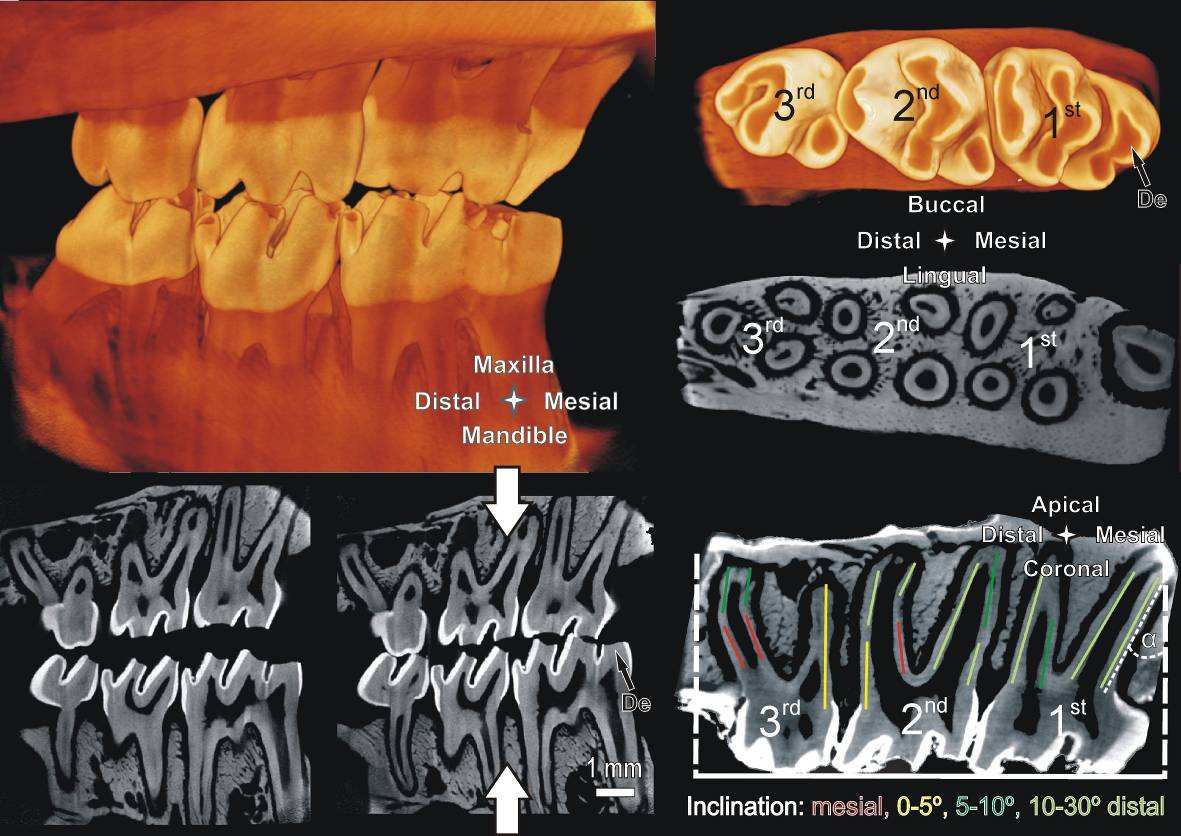
Fig. 1:
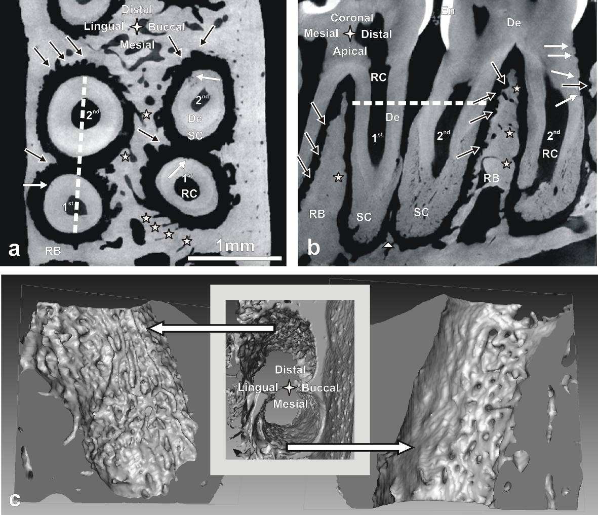
Fig. 2:
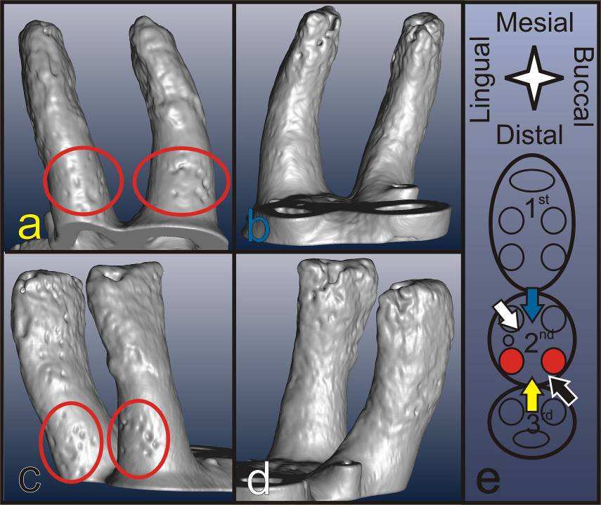
Fig. 3:
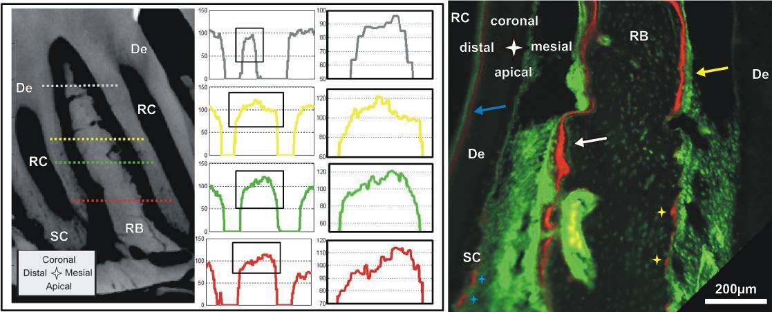
Fig. 4:
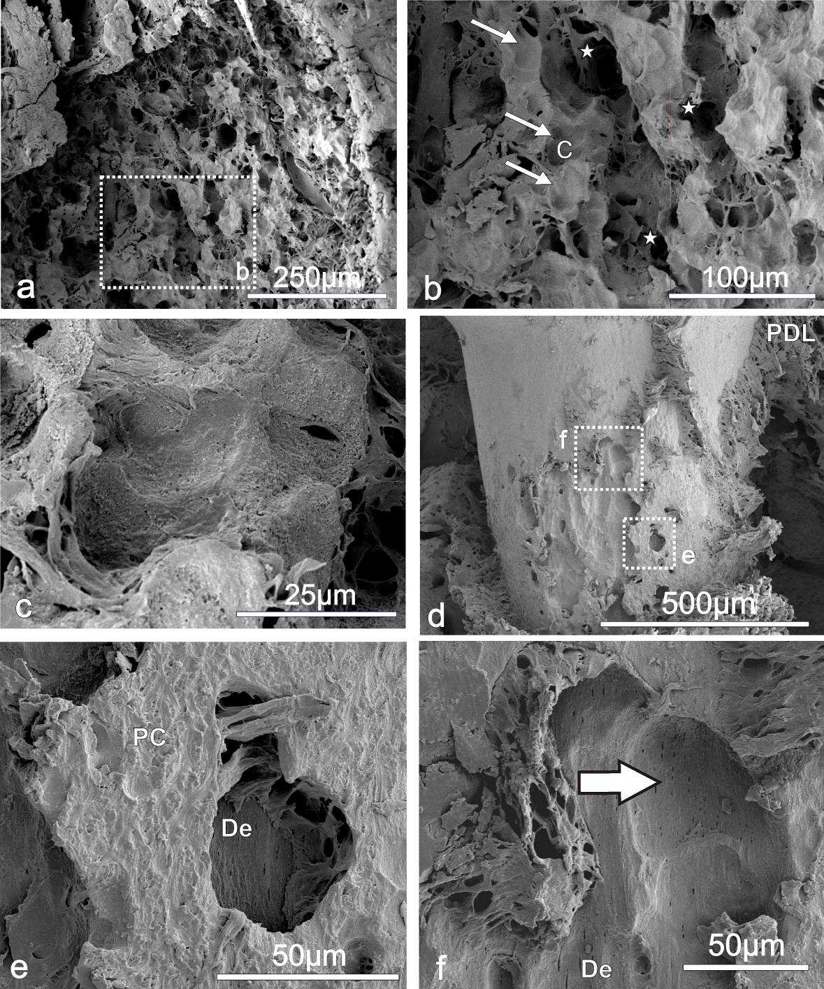
Fig. 5:
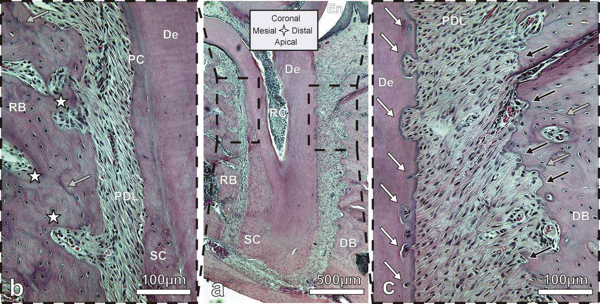
Fig. 6:
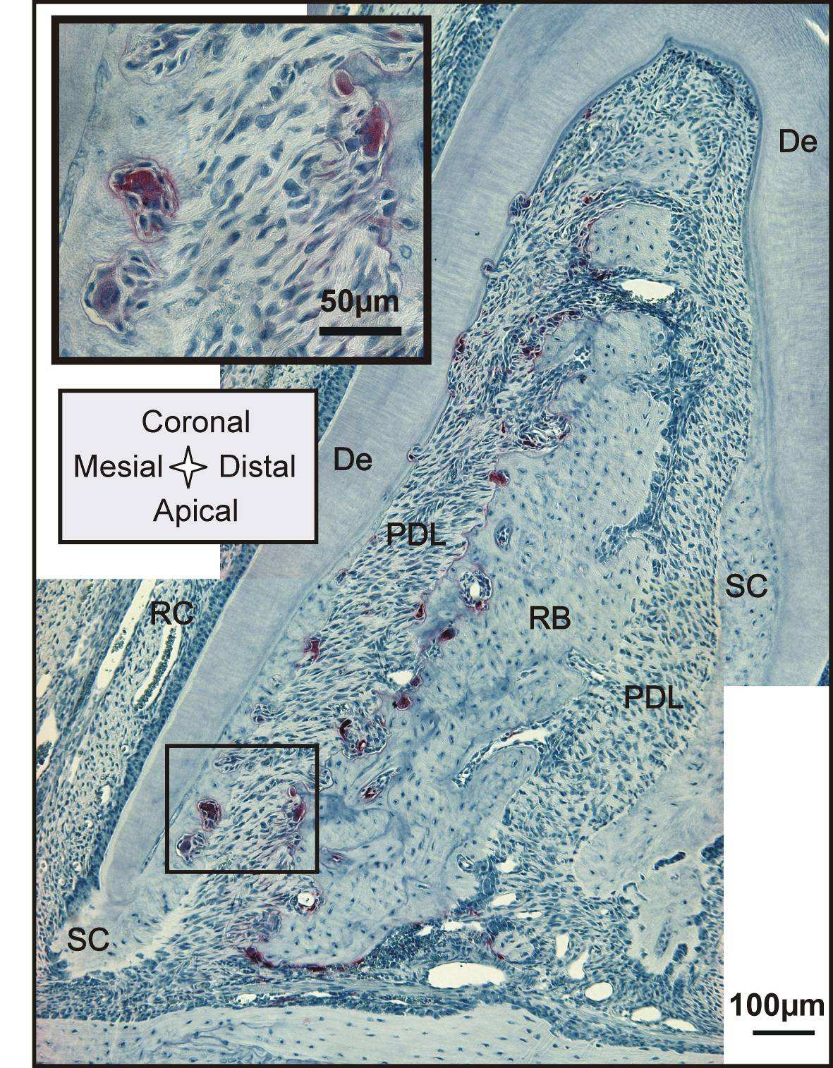
Fig. 7:
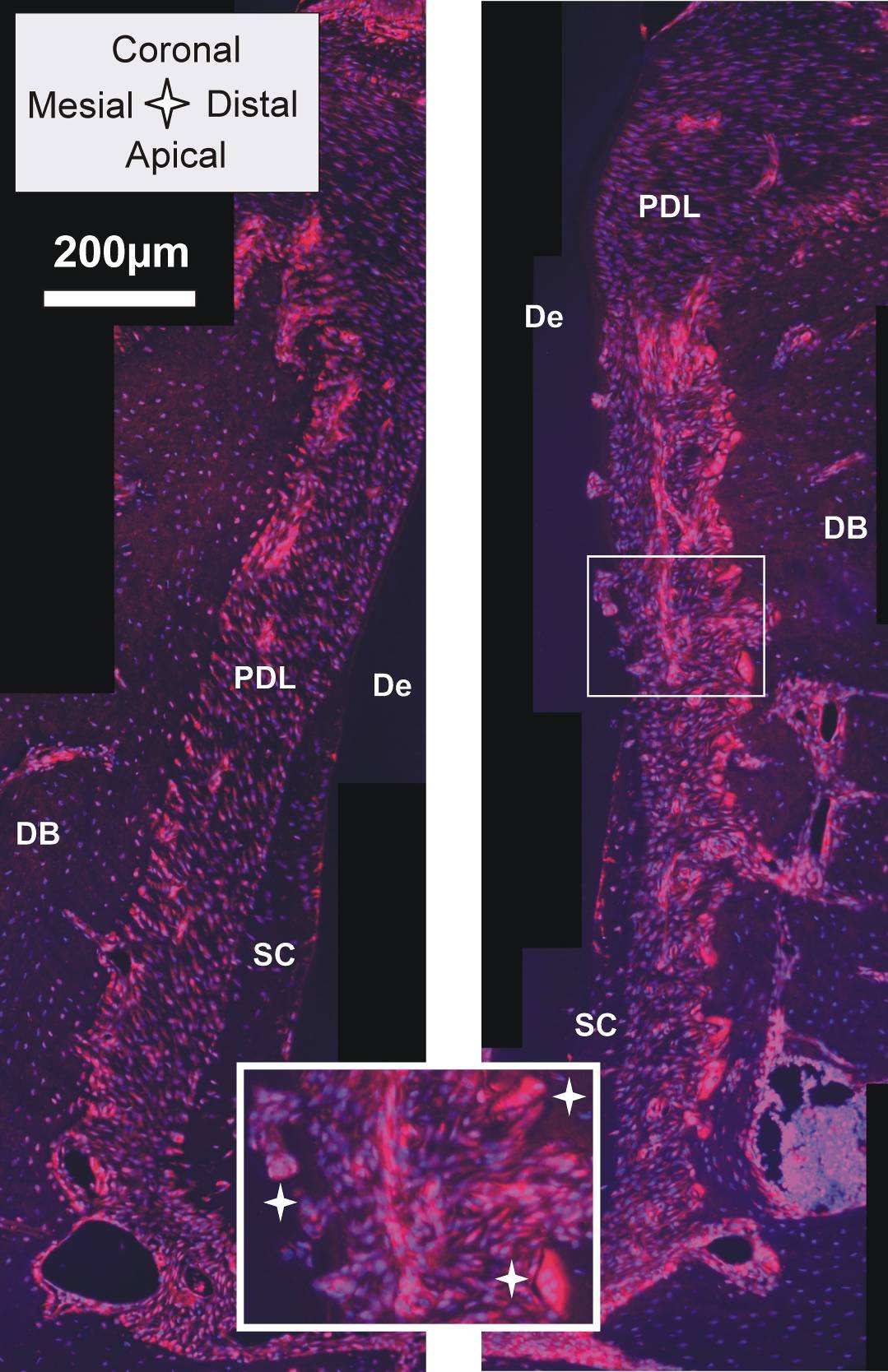
Fig. 8:
Fig. 9:
Source: http://www.herber.at/publications/Imaging.pdf
CATALOGO GENERALEGENERAL CATALOGUE made in Italy, made in F.A.R.G. Nei primi anni Sessanta ad Invorio, nella provincia di Novara, da sempre distretto di eccellenza nella produzione dell'industriadella rubinetteria, Giampiero Conton inizia la sua attività fondando la Rubinetteria Conton. Inizialmente l'azienda ebbe comescopo principale la commercializzazione di materiale idrosanitario; l'intuito del fondatore e alcuni segnali provenienti dallaclientela fecero capire le aperture del mercato e la possibilità di investire con ottimi risultati nella produzione di rubinetti agalleggiante con relative sfere in materiale plastico e in rame, senza dover fare i conti con una concorrenza troppo numerosa.E' nel 1996 che nasce F.A.R.G., naturale evoluzione di Rubinetteria Conton, che opera oggi su un'area di circa 15.000 mq dicui 5.000 mq coperti dedicati ai processi produttivi. Nel tempo la gamma dei prodotti si è ampliata con l'introduzione dialcuni componenti per impianti idrosanitari mantenendo la garanzia di qualità attestata da una produzione interamente ‘Made in Italy'. La costante attenzione della qualità, l'utilizzo di tecnologie avanzate e una rete di vendita che si avvale dellacollaborazione di agenti presenti sul territorio, hanno portato l'azienda a imporsi sul mercato nazionale e su quello estero.
PUSH DRAFT ECONOMIC DEVELOPMENT STRATEGY CONSULTATION Start: 21st July 2010 End: 21st September 2010 Table of Contents Foreward ………………………………….….3 Executive Summary.5 Questions.7 Your Views.8 How to Respond.9 Next Steps.9 Annex A – List of consultees.9 Foreword This Economic Development Strategy sets out our ambitions for the PUSH area in the light of substantial changes to the economic and policy environment since we developed our previous strategy. Our fundamental ambitions have not changed. We wish to see a more prosperous future for the residents of South Hampshire. We wish to see everyone sharing in the benefits, with reduced levels of deprivation and increased levels of labour market participation. We wish to see our cities fulfil their potential as engines of economic growth and we wish to see the sub-region becoming an even greater place to live, work and do business, offering a fantastic quality of life. In order to deliver this, our strategy is centred on sustainable development, on ensuring the quality of life which we value so highly is enhanced and enriched, not jeopardised. However, the context has changed. The recession has led to more of our residents becoming unemployed. It has created substantial challenges for both public and private sector investment both now and in the future. The change in Westminster government has changed the public policy environment. Whilst these changes could be seen as challenges, we see them as opportunities. They have forced us to look at how we work in this sub-region and how we can do things more efficiently. We must work together, pool our resources and align our priorities around a common agenda. We already have a track record of doing this in this sub-region. We are not starting from scratch, we are already ahead of the game. We therefore believe we can deliver higher levels of growth, we can deliver more and better for less, we can grasp the opportunities afforded to us through the changes being proposed by the Coalition. Central to our strategy is taking action to be innovative in how we deliver and fund activities. Central to our strategy is joining up the public and private sectors to work together. Central to our strategy is using the assets we already have in the sub-region; our people, our world class businesses; our universities and our fantastic natural environment. We have identified the areas of our economy where we need to invest and focus our efforts. Those sectors where we have great specialisms, world class innovation and skills and opportunities to drive economic output, those sectors which will underpin employment growth and create opportunities for our residents to access jobs and those sectors which are fundamental to South Hampshire offering a high quality of life.